Gigabyte did not go insane with the RGB accents, on either the packaging or the board. Set at default, Gigabyte stuck with a mostly dark approach and simple blue lighting. This gives the board a subdued, but still edgy look. The VRM heatsink is a mix of black and silver, which carries to the M.2 slot and even the PCH just to give a bit of continuity across the board.
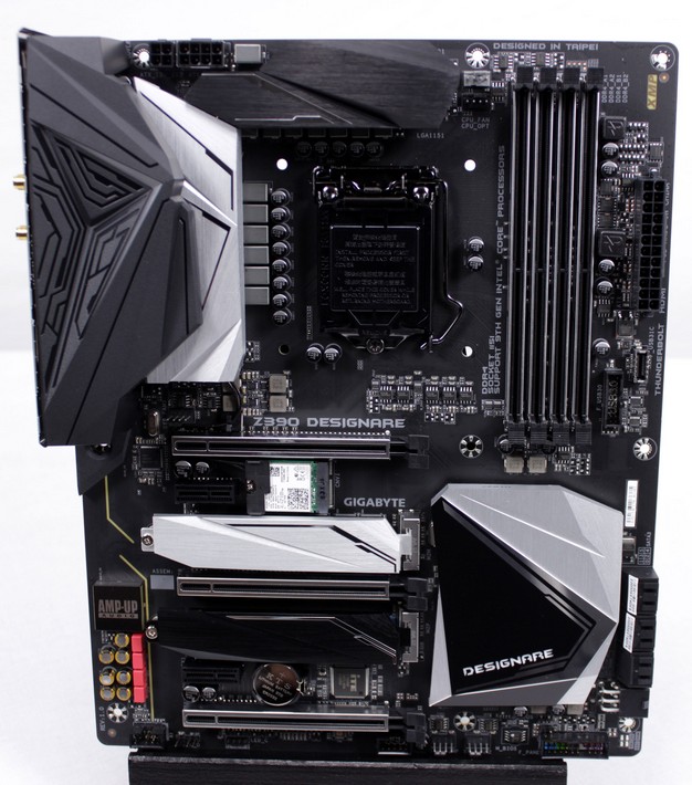
The Z390 Designare employs a massive looking VRM (Voltage Regulator Module) which we will get into later in detail; it is a 12+1 design. Below that we find the LGA1151 socket with support for 8th and 9th gen Intel CPUs. And this is not just for Intel Core series processors -- remember there are Celeron and Pentium models which the board supports too, although it would be a truly sad sight to pair one of those much lower end chips in this feature-rich, powerful board. The Z390 Designare also features 5 hybrid fan headers. They enable the connectors to be used for a bevy of devices such as pumps, flow meters, and normal coolers, to better match the cooling needs for your build.

The slot configuration may be of special interest for many here as well. Gigabyte specially engineered the
Designare board to be fitted for optimum connectivity and storage. This will be most apparent on the slot layout and the electrical PCIe lane layout. The
Designare supports two way
SLI/
Crossfire with
dual X8 PCIe, split from the CPU. If using a single card, the main PCIe slot will be full x16. For some
designers and creators, however, there may be a need for full-bandwidth adapter card storage solutions and Gigabyte has a solution for this. Most PCIe card SSDs will only use
a X4 lane, so the second GPU slot will be at X8 when populated
similar to the SLI configuration we mentioned previously. However, Gigabyte put a switch in the BIOS that will allow the 2nd GPU slot to share X4 lanes to the 3rd slot. The 3rd slot is normally a DMI fed X4 slot. This means you can now have a full X8-connected top slot for your GPU while having dual x4 slots of CPU PCIe lanes. This is a great option for PCIe based SSD storage and results
in maximum bandwidth for a storage solution, rather than having the SSDs fight with other devices for bandwidth through the X4 link of DMI between the PCH and the CPU.
Moving over to the right edge, we have six SATA ports which share some bandwidth with the M.2 slots. Be mindful of this fact when you populate them as the SATA drives may not show up if the port is shared with an installed M.2 Device. You can check the manual which has a full table breakdown of which slots will impact specific SATA ports. Also take note of the 6 pin PCIe power connector just below the SATA ports, which serves extra supplementary power. This is used should you place a massive multi card solution on the Designare board. The power port will help to offset the 24 pin power feed and allow less stress to be placed on the main PSU connector.
Along the bottom of the board, we see again a 6-pin PCIe power connector next to the front panel connector. Here you can also see a 4 LED array which will help signify where your board is at during the POST sequence for quick debugging. It is unfortunate not to see a 2 digit POST display as that is normally far more helpful should and issue arise, but at least GB has something here.
The audio solution of the Z390 Designare is no slouch, arriving with the ALC 1220VB codec, which is standard for most top end boards across all of the Z390 product stacks we have seen so far. The codec is backed by WIMA film and choice gold Nichicon caps to round out a competent audio solution. The amp is internal to the chipset choice and while normally we like to know what parts are pushing the audio, the ALC1220VB appears to be an all in one package and it should do the job well enough for most users.
Between the PCIe slots we find the CNVi WiFi module, which is great as it supports full Wave 2 WiFi along with Bluetooth 5. We especially like the attention to detail here as you can see a small plastic clip stuck onto the board next to the Z390 silk screening. This clip is there to route the wires for the CNVi module to the rear I/O, reducing the chance of damaging the wires or snagging them during installation. This kind of attention to detail is how you can tell that a manufacturer cares about making a good first impression for the customer.
The Rear I/O of this motherboard is very interesting. Mainstream 1151 CPUs typically have an iGPU, which means you can hook displays to the board directly without the need for a discrete GPU. When we saw the rear panel we thought "cool a Displayport and HDMI". Looking, closely the Displayport is an Input for feeding the signal from a discrete GPU through the Thunderbolt 3 ports. Keep in mind that the only iGPU fed port is the HDMI which is capable of 4K 30Hz. The Displayport input, however is DP1.4 which is 8K 60Hz capable as long as you have a GPU that can push said resolution.
Now that we've covered that connectivity oddity lets look at the actual connectors. The board has two USB 2.0 right above the multipurpose PS2 port. The red USB ports are USB 3.1 Gen 2 while the yellow are USB 3.0 (or 3.1 Gen 1) and are USB DAC UP enabled for higher power delivery. The dual screw type antennae headers are for connecting the CNVi WiFi. The Blue pair of USB ports are the same as the yellow just with the omission of the power delivery boost. Next up we have the dual Intel 1Gb LAN ports and the audio ports which support up to 7.1 channel surround sound, and also feature an optical S/PDIF pass through.
Now lets take a deeper dive into what really makes the Gigabyte Aorus Z390 Designare tick.
Here we'll dig into what makes this board work, which includes the VRM and the various chipsets, to control features.
The Aorus Z390 Designare employs what Gigabyte claims is a 12+1 VRM solution and when counting the inductors it shows 13. So, with that can we just assume the job is done right? While the VRM solution is nice and we feel like it needs a little attention so we'll undress this board a bit and see the configuration first hand.
CPU power is fed by a full EPS 8 pin along with a supplemental 4 pin. This is not really necessary for most situations, unless you plan to go sub-ambient at which point you have the possibility of drawing a lot of amps through the VRM. If your PSU only has a single CPU EPS 8 pin, do not worry. It will work just fine, even with an overclock on water cooling.
As we removed the VRM cooling, we have to take a moment to appreciate the beefy VRM sinks which are connected via heatpipe.
Here we see the VRM (Voltage Regulator Module) stripped. Notice that the VRM uses power stages versus individual driver MOSFETs. The power stages have driver/high/low side MOSFETs all in a single package which usually also have better monitoring and more finite control as well, which is good for tuning and stability.
Here we see a Vishay DrMOS SiC634 (50A) power stage which is used for the VCore; as mentioned there are 12 power stages on the board. There is also a Vishay DrMOS SIC620A (60A) power stage which is used for VccGT (iGPU). The VRM is controlled by an Intersil ISL69138 running in a 6+1 configuration. This means the VRM is using doublers to get to the 12 phases.
The doubler found on the rear of the board is an Intersil ISL6617A which is a smarter doubler that allows for full current balancing. Some doublers only split the PWM signal to two or more separate stages, but without the ability to balance current they never get out of phase with each other, which means they are not truly separate phases. The smarter doubler used here allows current balancing and control which means the 6 channels of the controller used for VCore, can better balance the individual power stages and can be considered as actual separate phases.
Here, we see a few of the key components powering the rear I/O. Starting at top left we have the Texas Instruments HD3SS215 which is a video switcher supporting
HDMI 4k60Hz. This we find funny as the
HDMI port here is only 30Hz per Gigabyte's spec sheet. Below that we find the DVI/HDMI
level shifter from NXPm, model number PTN3360DBS, This is basically an integrated
DisplayPort to HDMI or DVI adapter. To the right of
those we have dual Texas Instruments TPS65983BA, which is a Type C USB PD Controller and multiplexer chip for the dual Type C ports on the rear.
Lastly, we have the Intel Thunderbolt controller, model JHL7540, which is a dual port controller supporting Gen 3 and DisplayPort 1.4
Now that we've dug into how the board works, lets get it strapped to the bench and fired up.


